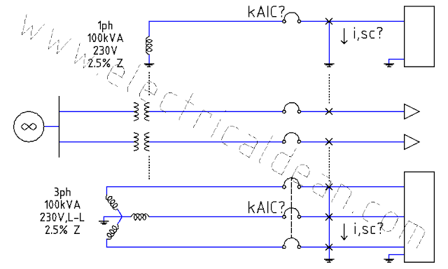
This post demonstrates how to estimate the kiloAmpere Interrupting Capacity (kAIC) rating of the first circuit breaker at the secondary side of a transformer using the Infinite Bus Method. The method assumes infinite supply from the primary side with negligible line impedances. Below is a modified version of Example D13 (Available Short Circuit Current) in Appendix D of the 2017 Philippine Electrical Code (PEC). SITUATION Two adjacent buildings are supplied by two different distribution transformers. One transformer is single-phase rated 100kVA, 230V with 2.5% impedance. The other is three-phase rated 100kVA, 230V line-to-line and also has 2.5% impedance. What minimum kAIC ratings are needed for the first circuit breakers down the line of each transformer to safely interrupt the maximum symmetrical fault currents? ANALYSIS 1.) SINGLE-PHASE TRANSFORMER LOAD-SIDE SUB-CIRCUIT Base Power, 1ph: S,base = 100kVA Base Voltage, 1ph: V,base = 230V Impedance, ...
RACEWAY SIZES (CONDUIT AND TUBING) 1.) Raceway Sizing There are three options for sizing raceways according to 2017 PEC Table 10.1.1.1 [ or 2017 NEC Chapter 9 Table 1 ], based on cross-sectional areas: A.) 53% raceway area for 1 conductor (a multiconductor cable is treated as a single conductor [Note 9]) B.) 31% raceway area for 2 conductors C.) 40% raceway area for over 2 conductors 1.1.) Choosing Between Alternatives For future expansion purposes, option (A) is far from practical. This may have use in very specific installations that are assumed to be not needing any expansions, but upgrades will definitely happen and option (A) will eventually become a bottleneck. Option (B) for 2 conductors having a smaller area than either option (A) for 1 conductor or option (C) for over 2 conductors may seem nonsensical, but it actually does make sense. Having 2 conductors usually means 2 live wires supplying loads that may require an equipment grounding conductor ...
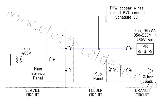
This post is inspired by the 2017 Philippine Electrical Code (PEC) Appendix D Example D12 (Voltage Regulators, Three-Phase). SITUATION A three-phase automatic voltage regulator (AVR) rated 30 kVA, 60 Hertz, 350-530 Volts input, 230 Volts output needs a feeder circuit from the main service panel. The AVR is installed in an air-conditioned data center with raised floors, and the conduit for electric conductors shall be run underneath. The wires to be used are made of copper conductors, with insulation rated for 75 degC operating temperature and of type THW (Thermoplastic, Heat-resistant, for Wet location). The raceway for the circuit is a rigid PVC Schedule 80 conduit. What size of 3ph circuit breaker, wires, and raceway are needed? ANALYSIS 1.) ONE-LINE DIAGRAM i,avr,1L ---> o|---V,msp,LN---V,avr,LN---|> 2.) CIRCUIT CALCULATIONS 2.1.) Kirchhoff's Voltage Law, LN: -V,msp,LN + V,avr,LN = 0 V,avr,LN = V,msp,LN 2...


Comments
Post a Comment