Why "Design Analysis"?
According to the Philippine Electrical Code (PEC), Article 1.3 (Electrical Plans and Specifications) states that the Plan Requirements (Section 1.3.2.1) are as follows:
(A) Location and Site Plans
(B) Legend or Symbols
(C) General Notes / Specifications
(D) Electrical Layout (Floor Plan)
(E) Schedule of Loads
(F) Design Analysis
(G) One Line Diagram
Details of each part shall be covered on a later post, but together, they provide a complete picture of the electrical system of a given project.
Parts A, B, D and G provide a "schematic overview" of the electrical system, while parts C and E provide an "elaborate description" of the nature and components of the electrical project.
Design Analysis (F), however, is the part that provides justification for the decisions made in the schematic arrangements and the component choices for the project. As such, it requires a quantitative approach to prove beyond any doubt that the electrical system is established based on solid engineering principles.
Design Analysis, then, is all about detailed calculations of, including but not limited to:
1. conductor and conduit sizes
2. overload protection ratings
3. voltage drops and surges
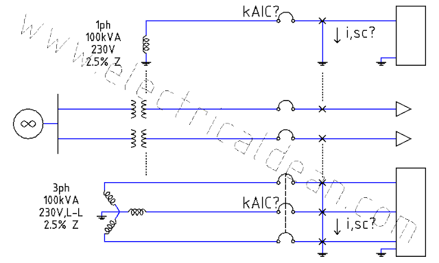
4. short-circuit or fault currents
5. overcurrent protection coordination
6. arc-flash hazards
7. harmonics and transients
8. illumination and electromagnetics
9. power and torque loads
10. other relevant electrical matters
The posts on this site are dedicated to Electrical Design Analysis, and may, from time to time, address related technical topics. The goal is to guide the reader in learning about electrical standards, safety practices, performance benchmarks, and electrical engineering in general.


Comments
Post a Comment