Faults - Scenario 1
The 2017 PEC approach is simple and straightforward, but it does not indicate the relationships of the parameters relative to each other.
This calculation is geared towards providing clarity to the confused electrical practitioner.
SITUATION
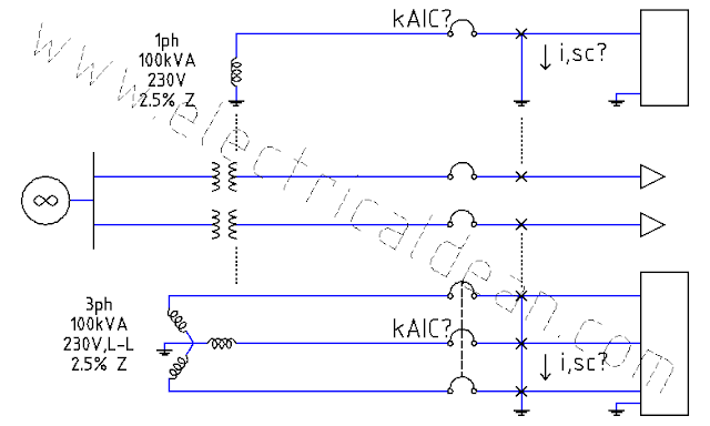
A fault occurs down the line of a single-phase transformer rated 100kVA, 230 Volts, and 2.5% impedance. What is the maximum symmetrical fault current produced?

ANALYSIS
1.) TRANSFORMER LOAD-SIDE SUB-CIRCUIT
Base power, 1ph: S,base = 100kVA
Base voltage, 1ph: V,base = 230V
Impedance, given: Z = 2.5% = 0.025 pu
2.) METHOD USING ACTUAL VALUES
2.1.) Base impedance, 1ph:
Z,base = (V,base)^2 / S,base
Z,base = (230V)^2 / 100kVA
Z,base = 0.529 ohm
2.2.) Actual impedance, 1ph:
Z,1ph = Z,base * Z,pu
Z,1ph = 0.529 ohm * 0.025 pu
Z,1ph = 0.013225 ohm
2.3.) Use rated voltage as actual voltage.
V,rated = 230V
2.4.) Short-circuit current, 1ph:
i,sc = V,rated / Z,1ph
i,sc = 230V / 0.013225 ohm
i,sc = 17,391.304 A
3.) METHOD USING PER-UNIT VALUES
3.1.) Base current, 1ph:
i,base = S,base / V,base
i,base = 100kVA / 230V
i,base = 434.78261 A
3.2.) Use rated voltage as reference.
V,pu = V,rated / V,base
V,pu = 230V / 230V
V,pu = 1 pu
3.3.) Short-circuit current, per-unit:
i,pu = V,pu / Z,pu
i,pu = 1 / 0.025 = 40 pu
3.4.) Short-circuit current, 1ph:
i,sc = i,pu * i,base
i,sc = 40pu * 434.78261 A
i,sc = 17,391.304 A
CONCLUSION
The maximum symmetrical fault current produced is 17.39 kiloAmps at the secondary side of the transformer.
Even at residential level of 230 Volts, short circuits are potentially dangerous and an ever-present concern. Electrical practitioners need to be aware of this.
Fault current calculations aid in the selection of circuit breakers with appropriate kiloAmpere Interrupting Capacity (kAIC) to avoid fires from explosions and arc flash incidents.
The technique used here is known as the Infinite Bus Method. It shows the maximum fault current by assuming infinite supply capacity with zero impedance connected to the bus at the primary side.
But if active motors are present at the secondary side, the fault current gets even bigger due to motor contribution. Refer to 2017 PEC Example D14 (Simplified Fault Current Calculation) Step 10.2.

Comments
Post a Comment