Faults - Note 1
In 2017 PEC Appendix D Example D14 Steps 10.2.d and 10.3.d, computing the fault currents yields almost 19,000 Amperes for point "b" and 11,000 Amperes for point "c". However, this same example as presented in the previous scenario results in fault currents of only around 17,000 Amperes for point "b" and 10,000 Amperes for point "c".
Why are they different?

ANALYSIS
1.) PROCEDURE IN 2017 PEC EXAMPLE D14
By inspection, it can be verified that all values in 2017 PEC D14 and in the previous scenario are almost identical, except for the new motor per-unit values used in the impedance diagrams of 2017 PEC D14 Steps 10.2.b and 10.3.b.
1.1.) 2017 PEC D14 Step 8 Motor Contribution
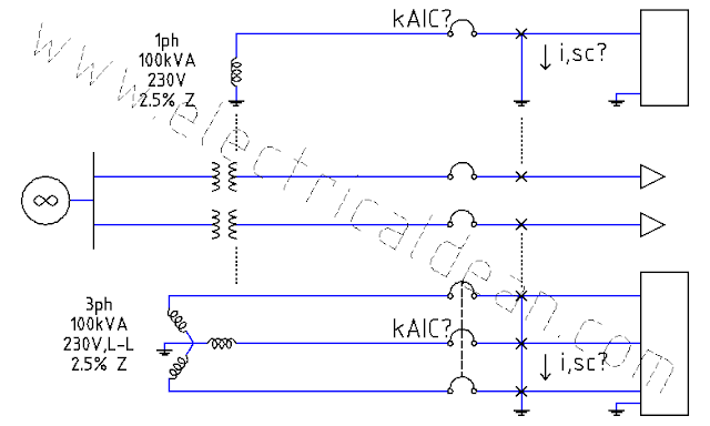
In this step, the motor per-unit impedance is initially estimated at 0.25 pu (equivalent to a 25% subtransient reactance neglecting resistance), after considering the recommendation in IEEE Std 141-1993 Section 4.5.4.1.
Conversion to the common base power yields a new motor per-unit impedance is 0.75 pu, just like in the previous scenario.
pu Zm = kVA base / (motor kVA / motor impedance)
pu Zm = 300 kVA / (100 kVA / 0.25 pu)
pu Zm = 0.75 pu
1.2.) 2017 PEC D14 Steps 10.2.b and 10.3.b Diagrams
The impedance diagrams in these steps present the per-unit value of each motor as 0.375 pu instead of 0.75 pu, without any explanation.
1.2.1.) 2017 PEC D14 Step 10.2.b Impedance Diagram
o|---E---|----Zs---Zt----|---"b"---|>
         |---Zm1---Zw1---|
         |---Zm2---Zw2---|
Zs = 0.0003, Zt = 0.05
Zm1 = 0.375, Zw1 = 0.031
Zm2 = 0.375, Zw2 = 0.031
1.2.2.) 2017 PEC D14 Step 10.3.b Impedance Diagram
o|---E---|----Zs---Zt----|---Zw3---"c"---|>
         |---Zm1---Zw1---|
         |---Zm2---Zw2---|
Zs = 0.0003, Zt = 0.05
Zm1 = 0.375, Zw1 = 0.031
Zm2 = 0.375, Zw2 = 0.031
Zw3 = 0.031
1.3.) 2017 PEC D14 Steps 10.2.d and 10.3.d Fault Currents
Using 0.375 pu as the new motor per-unit impedance, the fault calculations yield as follows.
1.3.1.) 2017 PEC D14 Step 10.2.d Fault Current at Point "b"
i,b,sc = (E / Z,b,pu) * S,base,new / (sqrt(3) * V,base)
Z,b,pu = (Zs + Zt) || (Zm1 + Zw1) || (Zm2 + Zw2)
Z,b,pu = 1 / [ 1/(Zs + Zt) + 1/(Zm1 + Zw1) +1/(Zm2 + Zw2) ]
Z,b,pu = 1 / [ 1/(0.0003 + 0.05) + 1/(0.375 + 0.031) + 1/(0.375 + 0.031) ]
Z,b,pu = 0.0403 pu
i,b,sc = (1 / 0.0403) * 300 kVA / (sqrt(3) * 230 V)
i,b,sc = 18,686.49 A
i,b,sc ~ 19,000 Amps
1.3.2.) 2017 PEC D14 Step 10.3.d Fault Current at Point "c"
i,c,sc = (E / Z,c,pu) * S,base,new / (sqrt(3) * V,base)
Z,c,pu = [ (Zs + Zt) || (Zm1 + Zw1) || (Zm2 + Zw2) ] + Zw3
Z,c,pu = [ 1 / [ 1/(Zs + Zt) + 1/(Zm1 + Zw1) +1/(Zm2 + Zw2) ] ] + Zw3
Z,c,pu = [ 1 / [ 1/(0.0003 + 0.05) + 1/(0.375 + 0.031) + 1/(0.375 + 0.031) ] ] + 0.031
Z,c,pu = 0.0403 + 0.031
Z,c,pu = 0.0713 pu
i,c,sc = (1 / 0.0713) * 300 kVA / (sqrt(3) * 230 V)
i,c,sc = 10,561.93 A
i,c,sc ~ 11,000 Amps
2.) RECOMPUTED 2017 PEC EXAMPLE D14
If 0.75 pu was used as the new motor per-unit impedance however, the results in 2017 PEC D14 Steps 10.2.d and 10.3.d would have been different.
2.1.) RECOMPUTED 2017 PEC D14 Step 10.2.d Fault Current at Point "b"
i,b,sc = (E / Z,b,pu) * S,base,new / (sqrt(3) * V,base)
Z,b,pu = (Zs + Zt) || (Zm1 + Zw1) || (Zm2 + Zw2)
Z,b,pu = 1 / [ 1/(Zs + Zt) + 1/(Zm1 + Zw1) +1/(Zm2 + Zw2) ]
Z,b,pu = 1 / [ 1/(0.0003 + 0.05) + 1/(0.75 + 0.031) + 1/(0.75 + 0.031) ]
Z,b,pu = 0.0446 pu
i,b,sc = (1 / 0.0446) * 300 kVA / (sqrt(3) * 230 V)
i,b,sc = 16,370.99 A
i,b,sc ~ 16,000 Amps (17,000 Amps if ceiling value is considered for breaker safety)
This coincides with the previous scenario which yielded 16.9 kiloAmps at fault point "b".
2.2.) RECOMPUTED 2017 PEC D14 Step 10.3.d Fault Current at Point "c"
i,c,sc = (E / Z,c,pu) * S,base,new / (sqrt(3) * V,base)
Z,c,pu = [ (Zs + Zt) || (Zm1 + Zw1) || (Zm2 + Zw2) ] + Zw3
Z,c,pu = [ 1 / [ 1/(Zs + Zt) + 1/(Zm1 + Zw1) +1/(Zm2 + Zw2) ] ] + Zw3
Z,c,pu = [ 1 / [ 1/(0.0003 + 0.05) + 1/(0.75 + 0.031) + 1/(0.75 + 0.031) ] ] + 0.031
Z,c,pu = 0.0446 + 0.031
Z,c,pu = 0.0756 pu
i,c,sc = (1 / 0.0756) * 300 kVA / (sqrt(3) * 230 V)
i,c,sc = 9,961.18 A
i,c,sc ~ 10,000 Amps
This coincides with the previous scenario which yielded 9.9 kiloAmps at fault point "c".
3.) SIMILAR EXAMPLE IN IEEE STD 141-1993
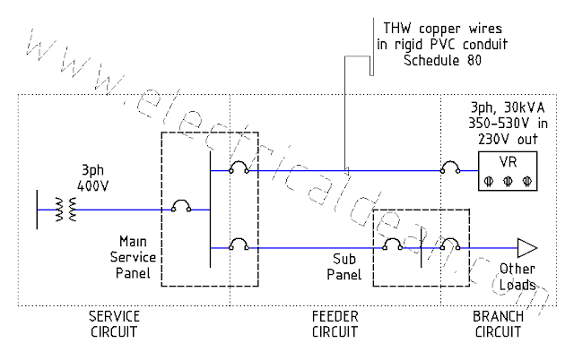
To further give credence to the results in the previous scenario, there is a similar example in IEEE Std 141-1993 (IEEE Recommended Practice for Electric Power Distribution for Industrial Plants) where the computed per-unit values are used as is in the diagrams and succeeding fault calculations.
IEEE Std 141-1993 Section 4.7 [ Example of short-circuit current calculation for a low-voltage system (under 1000 V) ] demonstrates the procedure.
3.1.) IEEE Std 141-1993 Section 4.7.1 Step 1(f) Motor Contribution
In this step, the motor per-unit impedances are converted to a common base power of 1,000 kVA, with an assumption that 1 Hp of mechanical output is derived from 1 kVA of electrical input.
[ 1 kVA * 93.25% power factor * 80% efficiency = 746 W = 1 Hp ]
3.1.1.) Motor Loads at Motor Control Center 1
Motor power = 400 Hp (~ 400kVA)
Subtransient reactance Xm1 = 25%
Motor X/R ratio = 6
Motor resistance Rm1 = 4.167%
pu Rm1 = (%Rm1 / 100) * (base kVA / motor kVA)
pu Rm1 = (4.167 / 100) * (1,000 kVA / 400 kVA)
pu Rm1 = 0.1042 pu
pu Xm1 = (%Xm1 / 100) * (base kVA / motor kVA)
pu Xm1 = (25 / 100) * (1,000 kVA / 400 kVA)
pu Xm1 = 0.625 pu
3.1.2.) Motor Loads at Motor Control Center 2
Motor power = 500 Hp (~ 500kVA)
Subtransient reactance Xm1 = 25%
Motor X/R ratio = 6
Motor resistance Rm1 = 4.167%
pu Rm2 = (%Rm1 / 100) * (base kVA / motor kVA)
pu Rm2 = (4.167 / 100) * (1,000 kVA / 500 kVA)
pu Rm2 = 0.0833 pu
pu Xm2 = (%Xm1 / 100) * (base kVA / motor kVA)
pu Xm2 = (25 / 100) * (1,000 kVA / 400 kVA)
pu Xm2 = 0.5 pu
3.2.) IEEE Std 141-1993 Section 4.7.2 Step 2 Diagrams
The motor per-unit values in these diagrams conform with the computed per-unit values in IEEE Std 141-1993 Section 4.7.1 Step 1(f).
3.2.1.) IEEE Std 141-1993 Section 4.7.2 Step 2 Figure 4-21 Resistance Diagram
|---Rs---Rt1---|---Rc2---Rm2---|
               |---Rc1---Rm1---|
Rs = 0.00011 , Rt1 = 0.0121
Rc1 = 0.0352, Rm1 = 0.1042
Rc2 = 0.01597, Rm2 = 0.0833
The motor per-unit resistances are unaltered.
3.2.2.) IEEE Std 141-1993 Section 4.7.2 Step 2 Figure 4-22 Reactance Diagram
|---Xs---Xt1---|---Xc2---Xm2---|
               |---Xc1---Xm1---|
Xs = 0.00165, Xt1 = 0.0562
Xc1 = 0.0215, Xm1 = 0.625
Xc2 = 0.01098, Xm2 = 0.5
The motor per-unit reactances are unaltered.
CONCLUSION
Although the reason for using different motor per-unit values in the diagrams from that obtained in the computations is not explained in 2017 PEC Example D14, the procedure in the previous scenario conforms with that of the example in IEEE Std 141-1993.
Therefore, it could be either (1) the motor per-unit values used in the PEC diagrams are just honest mistakes that led to erroneous calculations, or (2) there is some other undocumented step where the motor per-unit values are set even lower, possibly to increase fault current estimates for the purpose of attaining bigger ratings of circuit breaker kiloAmpere Interrupting Capacity (kAIC) for better safety.
But whatever the case may be, only the standards committee responsible for preparing the Philippine Electrical Code can truly shed light on this matter.
==========
REFERENCES
1.) Philippine Electrical Code (SI Modernized Metric System)
1.1.) 2017 PEC Appendix D Example D14 Simplified Fault Current Calculation.
2.) IEEE Std 141-1993: IEEE Recommended Practice for Electric Power Distribution for Industrial Plants
2.1.) IEEE Std 141-1993 Section 4.5.4.1 First-cycle Duties for Fuses and Circuit Breakers.
2.2.) IEEE Std 141-1993 Section 4.7 Example of short-circuit current calculation for a low-voltage system (under 1000 V).

Comments
Post a Comment