Voltage - Scenario 1
This take on the problem removes the necessity of memorizing formulas, by guiding the confused electrical practitioner to understand the schematics, then apply the principles of KVL and KCL instead.
SITUATION
A three-phase transformer bank supplies 230 Volts line-line to a structure via three 250 mm^2 THWN copper conductors in steel conduit 15.2 meters long, where the main service panel draws a total of 295 Amperes. One of the circuits in the main service panel feeds a three-phase motor via three 5.5 mm^2 THWN copper conductors in steel conduit 30.5 meters long. This electric motor is rated 60 Hertz, 230 Volts line-line, and draws a full load current of 20 Amperes at 80% power factor.
How much voltage drops are felt at the main service panel and at the motor terminals, coming from the transformer bank?

ANALYSIS
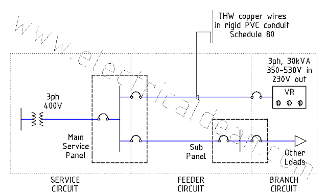
1.) ONE-LINE DIAGRAM
o|---V,xmr---Z,srv---|---Z,fdr---V,mtr---|>
                     |
                     |---Z,others---|>
2.) SERVICE CIRCUIT
2.1.) General Notes
2.1.1.) Definition
2017 PEC 1.1 [ or 2017 NEC 100 ] Definitions, Service: "The conductors and equipment for delivering electric energy from the serving utility to the wiring system of the premises served."
2.1.2.) Mandatory limits
2017 PEC 2.30.2.2(B) [ or 2017 NEC 230.23(B) ] Overhead Service Conductors, Minimum Size: "The conductors shall not be smaller than 8.0 mm^2 (3.2 mm dia) copper or 14 mm^2 aluminum or copper-clad aluminum."
2017 PEC 2.30.3.2(B) [ or 2017 NEC 230.31(B) ] Underground Service Conductors, Minimum Size: "The conductors shall not be smaller than8.0 mm^2 (3.2 mm dia) copper or 14 mm^2 aluminum or copper-clad aluminum."
2.2.) Service loop, 1ph:
                i,srv,1L --->

o|---V,xmr,LN---Z,srv,1L---V,msp,LN---|>
2.3.) Service conductor impedance, 1L:
2.3.1.) Specifications
The service conductors are 15.2 meters long per line, identified as 250 mm^2 THWN copper wires inside a steel conduit.
According to 2017 PEC Table 10.1.1.9 [ or 2017 NEC Chapter 9 Table 9 ] AC Resistance and Reactance for 600V Cables, the resistance and reactance for such specifications are 0.029 ohms per 305 meters and 0.048 ohms per 305 meters, respectively. [ 305 meters ~= 1,000 feet ]
2.3.2.) Applying vector methods
Z,srv,1L-> = [ R/m + j X/m ] * length
Z,srv,1L-> = [ (0.029 + j0.048) ohms / 305 m ] * 15.2 m
Z,srv,1L-> = R + jX
Z,srv,1L-> = (0.001445 + j0.002392) ohms
Z,srv,1L-> = Z,srv,1L < a
Z,srv,1L = sqrt(0.001445^2 + 0.002392^2)
Z,srv,1L = 0.002795 ohms
tan(a) = X / R
a = arctan(X / R)
a = arctan (0.002392 / 0.001445)
a = 58.86 deg
Z,srv,1L-> = 0.002795 ohms < 58.86 deg
2.4.) Service current, 1L:
According to 2017 PEC Table 3.10.2.6(B)(16) [ or 2017 NEC Table 310.15(B)(16) ] Insulated Conductor Ampacities in Raceway, the maximum allowable current for a 250 mm^2 THWN copper wire is 375 Amperes.
The total current passing through one line of the service circuit, due to all the loads in the circuits connected to the main service panel, is 295 Amperes. This is well within the specified current limit, hence the existing service conductor need not be replaced.
i,srv,1L = 295 Amps
2.5.) Voltage in the service conductors
2.5.1.) Line-Neutral:
V,srv,LN = i,srv,1L * Z,srv,1L
V,srv,LN = 295A * 0.002795 ohms
V,srv,LN = 0.8245 Volts
2.5.2.) Line-Line:
V,srv,LL = sqrt(3) * V,srv,LL
V,srv,LL = sqrt(3) * 0.8245V
V,srv,LL = 1.4281 Volts
2.6.) Voltage at the main service panel
2.6.1.) Total voltage drop from the transformer:
VD,msp,LL = V,srv,LL
VD,msp,LL = 1.4281 Volts
2.6.2.) Percent voltage drop from the transformer:
%VD,msp = (VD,msp,LL / V,xmr,LL) * 100
%VD,msp = (1.4281V / 230V) * 100
%VD,msp = (0.006209) * 100
%VD,msp = 0.6209%
2.6.3.) Terminal voltage, Line-Line:
V,msp,LL = V,xmr,LL - VD,msp,LL
V,msp,LL = 230V - 1.4281V
V,msp,LL = 228.5719 Volts
3.) FEEDER CIRCUIT
3.1.) General Notes
3.1.1.) Definition
2017 PEC 1.1 [ or 2017 NEC 100 ] Definitions, Feeder: "All circuit conductors between the service equipment, the source of a separately derived system, or other power supply source and the final branch-circuit overcurrent device."
3.2.) Feeder loop, 1ph:
                               i,fdr,1L --->

o|---V,xmr,LN---V,srv,LN---|---Z,fdr,1L---V,mtr,LN---|>
3.3.) Feeder conductor impedance, 1L:
3.3.1.) Specifications
The feeder conductors are 30.5 meters long per line, identified as 5.5 mm^2 THWN copper wires inside a steel conduit.
According to 2017 PEC Table 10.1.1.9 [ or 2017 NEC Chapter 9 Table 9 ] AC Resistance and Reactance for 600V Cables, the resistance and reactance for such specifications are 1.2 ohms per 305 meters and 0.063 ohms per 305 meters, respectively. [ 305 meters ~= 1,000 feet ]
3.3.2.) Applying vector methods
Z,fdr,1L-> = [ R/m + j X/m ] * length
Z,fdr,1L-> = [ (1.2 + j0.063) ohms / 305 m ] * 30.5 m
Z,fdr,1L-> = R + jX
Z,fdr,1L-> = (0.12 + j0.0063) ohms
Z,fdr,1L-> = Z,fdr,1L < a
Z,fdr,1L = sqrt(R^2 + X^2)
Z,fdr,1L = sqrt(0.12^2 + 0.0063^2)
Z,fdr,1L = 0.1202 ohms
tan(a) = X / R
a = arctan(X / R)
a = arctan (0.0063 / 0.12)
a = 3.01 deg
Z,fdr,1L-> = 0.1202 ohms < 3.01 deg
3.4.) Feeder current, 1L:
According to 2017 PEC Table 3.10.2.6(B)(16) [ or 2017 NEC Table 310.15(B)(16) ] Insulated Conductor Ampacities in Raceway, the maximum allowable current for a 5.5 mm^2 THWN copper wire is 35 Amperes.
The full-load current passing through one line of the feeder circuit to the motor is 20 Amperes. This is well within the specified current limit, hence the existing feeder conductor need not be replaced.
i,fdr,1L = 20 Amps
3.5.) Voltage in the feeder conductors
3.5.1.) Line-Neutral:
V,fdr,LN = i,fdr,1L * Z,fdr,1L
V,fdr,LN = 20A * 0.1202 ohms
V,fdr,LN = 2.404 Volts
3.5.2.) Line-Line:
V,fdr,LL = sqrt(3) * V,fdr,LL
V,fdr,LL = sqrt(3) * 2.404V
V,fdr,LL = 4.1639 Volts
3.6.) Voltage at the motor terminals
3.6.1.) Total voltage drop from the transformer:
VD,mtr,LL = V,srv,LL + V,fdr,LL
VD,mtr,LL = 1.4281V + 4.1639V
VD,mtr,LL = 5.592 Volts
3.6.2.) Percent voltage drop from the transformer:
%VD,mtr = (VD,mtr,LL / V,xmr,LL) * 100
%VD,mtr = (5.592V / 230V) * 100
%VD,mtr = (0.02431) * 100
%VD,mtr = 2.431%
3.6.3.) Terminal voltage, Line-Line:
V,mtr,LL = V,xmr,LL - VD,mtr,LL
V,mtr,LL = 230V - 5.592V
V,mtr,LL = 224.408 Volts
CONCLUSION
With the transformers supplying 230 Volts line-line, the voltage drop at the main service panel is only around 0.62%, resulting to an operating voltage of around 228.57 Volts line-line, while the voltage drop at the motor terminals is around 2.43%, resulting to an operating voltage of around 224.41 Volts line-line.
The 2017 Philippine Electrical Code [ or the American 2017 National Electrical Code (NFPA 70) ] have the following mandatory rules on voltage drops.
1.) MANDATORY RULES
1.1.) 2017 PEC 6.47.1.4(D) [ or 2017 NEC 647.4(D) ] Sensitive Electronic Equipment sets the maximum voltage drop at 1% to 1.5% for branch circuits (2% to 2.5% if feeders are included).
1.2.) 2017 PEC 6.95.1.7 [ or 2017 NEC 695.7 ] Fire Pumps sets the maximum voltage drop at 15% during starting and 5% during running conditions.
But elsewhere in the Code, voltage drop recommendations are mostly for informational purposes only. A maximum voltage drop of 3% for the farthest outlets (5% if feeders are included) will "provide reasonable efficiency of operation", as stated in these explanatory materials.
2.) EXPLANATORY MATERIALS
2.1.) 2017 PEC 2.10.2.2(A) FPN No. 4 [ or 2017 NEC 210.19(A) Info Note No. 4 ]
2.2.) 2017 PEC 2.15.1.2(A)(1) FPN No. 2 [ or 2017 NEC 215.2(A)(1) Info Note No. 2 ]
Although these informational voltage drop limits are not enforceable, common sense dictates that big voltage drops lead to lower operating voltages and thus affect the power equation (P=V*i). This results in either (1) lower current that inefficiently powers passive loads (such as lights), or (2) higher current that deteriorates insulation due to heat just to drive magnetic loads (such as induction motors).
It is, therefore, wise to give voltage drop limits due consideration.
For comparison, the next scenario demonstrates how the methods used here in a three-phase system can also be applied in single-phase systems with a few minor adjustments.
==========
REFERENCES
1.) Philippine Electrical Code (SI Modernized Metric System)
1.1.) 2017 PEC 1.1 Definitions, Feeder.
1.2.) 2017 PEC 1.1 Definitions, Service.
1.3.) 2017 PEC 2.10.2.2(A) FPN No. 4: Branch Circuits, Conductors - Minimum Ampacity and Size, Voltage Drop.
1.4.) 2017 PEC 2.15.1.2(A)(1) FPN No. 2: Feeders, Minimum Rating and Size, Voltage Drop.
1.5.) 2017 PEC 2.30.2.2(B) Overhead Service Conductors, Minimum Size.
1.6.) 2017 PEC 2.30.3.2(B) Underground Service Conductors, Minimum Size.
1.7.) 2017 PEC Table 3.10.2.6(B)(16) Allowable Ampacities of Insulated Conductors Rated Up to and Including 2000 Volts, 60degC Through 90degC, Not More Than Three Current-Carrying Conductors in Raceway, Cable, or Earth (Directly Buried), Based on Ambient Temperature of 30degC.
1.8.) 2017 PEC 6.47.1.4(D) Sensitive Electronic Equipment, Wiring Methods, Voltage Drop.
1.9.) 2017 PEC 6.95.1.7 Fire Pumps, Voltage Drop.
1.10.) 2017 PEC Table 10.1.1.9 Alternating-Current Resistance and Reactance for 600-Volt Cables, 3-Phase, 60Hz, 75degC - Three Single Conductors in Conduit.
1.11.) 2017 PEC Appendix D Example D15 Voltage Drop Calculation.
2.) National Electrical Code (US Inch-Pound System)
2.1.) 2017 NEC 100 Definitions, Feeder.
2.2.) 2017 NEC 100 Definitions, Service.
2.3.) 2017 NEC 210.19(A) Informational Note No. 4: Branch Circuits, Conductors - Minimum Ampacity and Size, Voltage Drop.
2.4.) 2017 NEC 215.2(A)(1) Informational Note No. 2: Feeders, Minimum Rating and Size, Voltage Drop.
2.5.) 2017 NEC 230.23(B) Overhead Service Conductors, Minimum Size.
2.6.) 2017 NEC 230.31(B) Underground Service Conductors, Minimum Size.
2.7.) 2017 NEC Table 310.15(B)(16) Allowable Ampacities of Insulated Conductors Rated Up to and Including 2000 Volts, 60degC Through 90degC (140degF Through 194degF), Not More Than Three Current-Carrying Conductors in Raceway, Cable, or Earth (Directly Buried), Based on Ambient Temperature of 30degC (86degF).
2.8.) 2017 NEC 647.4(D) Sensitive Electronic Equipment, Wiring Methods, Voltage Drop.
2.9.) 2017 NEC 695.7 Fire Pumps, Voltage Drop.
2.10.) 2017 NEC Chapter 9 Table 9 Alternating-Current Resistance and Reactance for 600-Volt Cables, 3-Phase, 60Hz, 75degC (167degF) - Three Single Conductors in Conduit.
2.11.) [Not found in 2017 NEC Annex D] (Voltage Drop Calculation).
Comments
Post a Comment