Voltage - Scenario 2
This post is a single-phase version of the three-phase example in the previous scenario. The same methods in understanding schematics and applying Kirchhoff's Laws are used, with minor adjustments in the loop diagrams and voltage calculations.
SITUATION
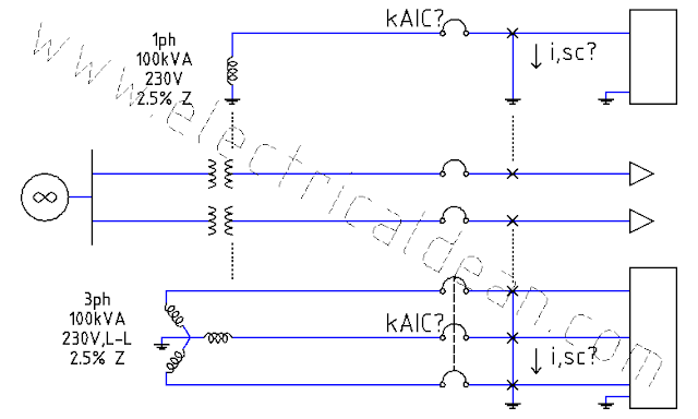
A single-phase transformer supplies 230 Volts to a structure via two 250 mm^2 THWN copper conductors in steel conduit 15.2 meters long, where the main service panel draws a total of 295 Amperes. One of the circuits in the main service panel feeds a single-phase motor via two 5.5 mm^2 THWN copper conductors in steel conduit 30.5 meters long. This electric motor is rated 60 Hertz, 230 Volts, and draws a full load current of 20 Amperes at 80% power factor.
How much voltage drops are felt at the main service panel and at the motor terminals, coming from the transformer?

ANALYSIS
1.) ONE-LINE DIAGRAM
o|---V,xmr---Z,srv---|---Z,fdr---V,mtr---|>
                     |
                     |---Z,others---|>
2.) SERVICE CIRCUIT
2.1.) General Notes
2.1.1.) Definition
2017 PEC 1.1 [ or 2017 NEC 100 ] Definitions, Service: "The conductors and equipment for delivering electric energy from the serving utility to the wiring system of the premises served."
2.1.2.) Mandatory limits
2017 PEC 2.30.2.2(B) [ or 2017 NEC 230.23(B) ] Overhead Service Conductors, Minimum Size: "The conductors shall not be smaller than 8.0 mm^2 (3.2 mm dia) copper or 14 mm^2 aluminum or copper-clad aluminum."
2017 PEC 2.30.3.2(B) [ or 2017 NEC 230.31(B) ] Underground Service Conductors, Minimum Size: "The conductors shall not be smaller than8.0 mm^2 (3.2 mm dia) copper or 14 mm^2 aluminum or copper-clad aluminum."
2.2.) Service loop, 1ph:
                 i,srv,1ph --->

o|---V,xmr,1ph---Z,srv,1L------|
                               |
                           V,msp,1ph
                               |
<|---------------Z,srv,1L------|

                 i,srv,1ph <---
2.3.) Service conductor impedance, 1L:
2.3.1.) Specifications
The service conductors are 15.2 meters long per line, identified as 250 mm^2 THWN copper wires inside a steel conduit.
According to 2017 PEC Table 10.1.1.9 [ or 2017 NEC Chapter 9 Table 9 ] AC Resistance and Reactance for 600V Cables, the resistance and reactance for such specifications are 0.029 ohms per 305 meters and 0.048 ohms per 305 meters, respectively. [ 305 meters ~= 1,000 feet ]
2.3.2.) Applying vector methods
Z,srv,1L-> = [ R/m + j X/m ] * length
Z,srv,1L-> = [ (0.029 + j0.048) ohms / 305 m ] * 15.2 m
Z,srv,1L-> = R + jX
Z,srv,1L-> = (0.001445 + j0.002392) ohms
Z,srv,1L-> = Z,srv,1L < a
Z,srv,1L = sqrt(0.001445^2 + 0.002392^2)
Z,srv,1L = 0.002795 ohms
tan(a) = X / R
a = arctan(X / R)
a = arctan (0.002392 / 0.001445)
a = 58.86 deg
Z,srv,1L-> = 0.002795 ohms < 58.86 deg
2.4.) Service current, 1ph:
According to 2017 PEC Table 3.10.2.6(B)(16) [ or 2017 NEC Table 310.15(B)(16) ] Insulated Conductor Ampacities in Raceway, the maximum allowable current for a 250 mm^2 THWN copper wire is 375 Amperes.
The total current passing through the service circuit, due to all the loads in the circuits connected to the main service panel, is 295 Amperes. This is well within the specified current limit, hence the existing service conductor need not be replaced.
i,srv,1ph = 295 Amps
2.5.) Voltage in the service conductors
Unlike three-phase systems where the current is distributed over three circuits "firing" their sine waves in succession "120 degrees" apart in the time domain [ | tan (120 deg) | = square root of 3 ], the current in a single-phase system is concentrated on one circuit composed of two lines (entry and return) that effectively double the conductor impedance. This consequently doubles the voltage drop felt at the load-side of the circuit.
2.5.1.) One line:
V,srv,1L = i,srv,1ph * Z,srv,1L
V,srv,1L = 295A * 0.002795 ohms
V,srv,1L = 0.8245 Volts
2.5.2.) Two lines in one phase:
V,srv,1ph = 2 * V,srv,1L
V,srv,1ph = 2 * 0.8245V
V,srv,1ph = 1.649 Volts
2.6.) Voltage at the main service panel
2.6.1.) Total voltage drop from the transformer:
VD,msp,1ph = V,srv,1ph
VD,msp,1ph = 1.649 Volts
2.6.2.) Percent voltage drop from the transformer:
%VD,msp = (VD,msp,1ph / V,xmr,1ph) * 100
%VD,msp = (1.649V / 230V) * 100
%VD,msp = (0.00717) * 100
%VD,msp = 0.717%
2.6.3.) Terminal voltage, 1ph:
V,msp,1ph = V,xmr,1ph - VD,msp,1ph
V,msp,1ph = 230V - 1.649V
V,msp,1ph = 228.351 Volts
3.) FEEDER CIRCUIT
3.1.) General Notes
3.1.1.) Definition
2017 PEC 1.1 [ or 2017 NEC 100 ] Definitions, Feeder: "All circuit conductors between the service equipment, the source of a separately derived system, or other power supply source and the final branch-circuit overcurrent device."
3.2.) Feeder loop, 1ph:
                                 i,fdr,1ph --->

o|---V,xmr,1ph---V,srv,1ph---|---Z,fdr,1L------|
                                               |
                                           V,mtr,1ph
                                               |
<|---------------------------|---Z,fdr,1L------|

                                 i,fdr,1ph <---
3.3.) Feeder conductor impedance, 1L:
3.3.1.) Specifications
The feeder conductors are 30.5 meters long per line, identified as 5.5 mm^2 THWN copper wires inside a steel conduit.
According to 2017 PEC Table 10.1.1.9 [ or 2017 NEC Chapter 9 Table 9 ] AC Resistance and Reactance for 600V Cables, the resistance and reactance for such specifications are 1.2 ohms per 305 meters and 0.063 ohms per 305 meters, respectively. [ 305 meters ~= 1,000 feet ]
3.3.2.) Applying vector methods
Z,fdr,1L-> = [ R/m + j X/m ] * length
Z,fdr,1L-> = [ (1.2 + j0.063) ohms / 305 m ] * 30.5 m
Z,fdr,1L-> = R + jX
Z,fdr,1L-> = (0.12 + j0.0063) ohms
Z,fdr,1L-> = Z,fdr,1L < a
Z,fdr,1L = sqrt(R^2 + X^2)
Z,fdr,1L = sqrt(0.12^2 + 0.0063^2)
Z,fdr,1L = 0.1202 ohms
tan(a) = X / R
a = arctan(X / R)
a = arctan (0.0063 / 0.12)
a = 3.01 deg
Z,fdr,1L-> = 0.1202 ohms < 3.01 deg
3.4.) Feeder current, 1ph:
According to 2017 PEC Table 3.10.2.6(B)(16) [ or 2017 NEC Table 310.15(B)(16) ] Insulated Conductor Ampacities in Raceway, the maximum allowable current for a 5.5 mm^2 THWN copper wire is 35 Amperes.
The full-load current passing through the feeder circuit to the motor is 20 Amperes. This is well within the specified current limit, hence the existing feeder conductor need not be replaced.
i,fdr,1ph = 20 Amps
3.5.) Voltage in the feeder conductor
Unlike three-phase systems where the current is distributed over three circuits "firing" their sine waves in succession "120 degrees" apart in the time domain [ | tan 120 deg | = square root of 3 ], the current in a single-phase system is concentrated on one circuit composed of two lines (entry and return) that effectively double the conductor impedance. This consequently doubles the voltage drop felt at the load-side of the circuit.
3.5.1.) One line:
V,fdr,1L = i,fdr,1ph * Z,fdr,1L
V,fdr,1L = 20A * 0.1202 ohms
V,fdr,1L = 2.404 Volts
3.5.2.) Two lines in one phase:
V,fdr,1ph = 2 * V,fdr,1L
V,fdr,1ph = 2 * 2.404V
V,fdr,1ph = 4.808 Volts
3.6.) Voltage at the motor terminals
3.6.1.) Total voltage drop from the transformer:
VD,mtr,1ph = V,srv,1ph + V,fdr,1ph
VD,mtr,1ph = 1.649V + 4.808V
VD,mtr,1ph = 6.457 Volts
3.6.2.) Percent voltage drop from the transformer:
%VD,mtr = (VD,mtr,1ph / V,xmr,1ph) * 100
%VD,mtr = (6.457V / 230V) * 100
%VD,mtr = (0.02807) * 100
%VD,mtr = 2.807%
3.6.3.) Terminal voltage, 1ph:
V,mtr,1ph = V,xmr,1ph - VD,mtr,1ph
V,mtr,1ph = 230V - 6.457V
V,mtr,1ph = 223.543 Volts
CONCLUSION
With the transformer supplying 230 Volts, the voltage drop at the main service panel is only around 0.717%, resulting to an operating voltage of around 228.351 Volts, while the voltage drop at the motor terminals is around 2.807%, resulting to an operating voltage of around 223.543 Volts.
For information on the mandatory rules and explanatory materials related to voltage drop in 2017 PEC [or 2017 NEC], refer to Conclusion sections 1 and 2 in the previous scenario.
==========
REFERENCES
1.) Philippine Electrical Code (SI Modernized Metric System)
1.1.) 2017 PEC 1.1 Definitions, Feeder.
1.2.) 2017 PEC 1.1 Definitions, Service.
1.3.) 2017 PEC 2.30.2.2(B) Overhead Service Conductors, Minimum Size.
1.4.) 2017 PEC 2.30.3.2(B) Underground Service Conductors, Minimum Size.
1.5.) 2017 PEC Table 3.10.2.6(B)(16) Allowable Ampacities of Insulated Conductors Rated Up to and Including 2000 Volts, 60degC Through 90degC, Not More Than Three Current-Carrying Conductors in Raceway, Cable, or Earth (Directly Buried), Based on Ambient Temperature of 30degC.
1.6.) 2017 PEC Table 10.1.1.9 Alternating-Current Resistance and Reactance for 600-Volt Cables, 3-Phase, 60Hz, 75degC - Three Single Conductors in Conduit.
1.7.) 2017 PEC Appendix D Example D15 Voltage Drop Calculation.
2.) National Electrical Code (US Inch-Pound System)
2.1.) 2017 NEC 100 Definitions, Feeder.
2.2.) 2017 NEC 100 Definitions, Service.
2.3.) 2017 NEC 230.23(B) Overhead Service Conductors, Minimum Size.
2.4.) 2017 NEC 230.31(B) Underground Service Conductors, Minimum Size.
2.5.) 2017 NEC Table 310.15(B)(16) Allowable Ampacities of Insulated Conductors Rated Up to and Including 2000 Volts, 60degC Through 90degC (140degF Through 194degF), Not More Than Three Current-Carrying Conductors in Raceway, Cable, or Earth (Directly Buried), Based on Ambient Temperature of 30degC (86degF).
2.6.) 2017 NEC Chapter 9 Table 9 Alternating-Current Resistance and Reactance for 600-Volt Cables, 3-Phase, 60Hz, 75degC (167degF) - Three Single Conductors in Conduit.
2.7.) [Not found in 2017 NEC Annex D] (Voltage Drop Calculation).
Comments
Post a Comment