Standards - Scenario 2
SITUATION
A three-phase automatic voltage regulator (AVR) rated 30 kVA, 60 Hertz, 350-530 Volts input, 230 Volts output needs a feeder circuit from the main service panel. The AVR is installed in an air-conditioned data center with raised floors, and the conduit for electric conductors shall be run underneath.
The wires to be used are made of copper conductors, with insulation rated for 75 degC operating temperature and of type THW (Thermoplastic, Heat-resistant, for Wet location). The raceway for the circuit is a rigid PVC Schedule 80 conduit.
What size of 3ph circuit breaker, wires, and raceway are needed?

ANALYSIS
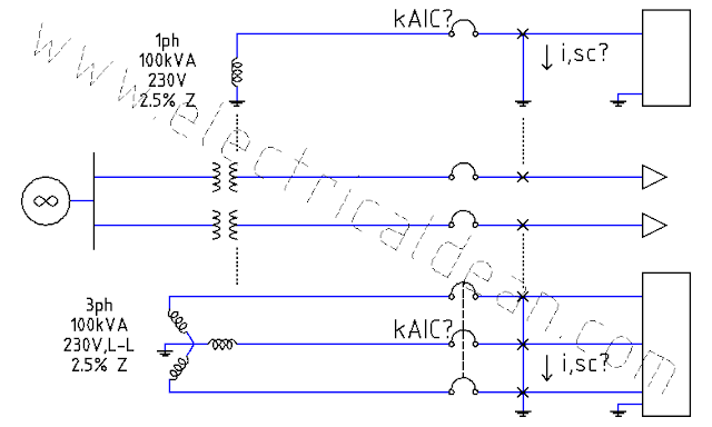
1.) ONE-LINE DIAGRAM
             i,avr,1L --->

o|---V,msp,LN---V,avr,LN---|>
2.) CIRCUIT CALCULATIONS
2.1.) Kirchhoff's Voltage Law, LN:
-V,msp,LN + V,avr,LN = 0
V,avr,LN = V,msp,LN
2.2.) Power equation, 3ph:
S,avr,3ph = 3 V,avr,LN * i,avr,1L
S,avr,3ph = 3 V,msp,LN * i,avr,1L
V,msp,LN = V,msp,LL / sqrt(3)
S,avr,3ph = 3 (V,msp,LL / sqrt(3)) * i,avr,1L
S,avr,3ph = sqrt(3) * V,msp,LL * i,avr,1L
i,avr,1L = S,avr,3ph / (sqrt(3) * V,msp,LL)
2.3.) Full-load current, 1ph:
The power equations show that voltage is inversely proportional to the current. To maintain the same amount of power delivered to the load, the amount of current drawn by the AVR increases when the voltage at the main service panel decreases. Therefore, the lower voltage rating shall be used to calculate the maximum current drawn at full-load power.
S,avr,3ph = 30 kVA
V,msp,LL = 350 V
i,avr,1L = 30kVA / (sqrt(3) * 350V)
i,avr,1L = 30000VA / (sqrt(3) * 350V)
i,avr,1L = 49.4872 A
3.) SPECIFICATIONS
3.1.) The circuit breaker trip rating shall not be less than 125% of the maximum steady-state current (from both continuous and noncontinuous loads) of the circuit.
(Above the minimum requirements of 2017 PEC 2.15.1.3 [ or 2017 NEC 215.3 ] Feeders, Overcurrent Protection.)
3.2.) The wire ampacity shall not be less than the circuit breaker trip rating, to ensure that the breaker opens before wire insulators burn and cause fire.
(Above the minimum requirements of 2017 PEC 2.15.1.2(A)(1)(a) [ or 2017 NEC 215.2(A)(1)(a) ] Feeders Not More Than 600 Volts.)
3.3.) The raceway shall be filled only up to 40% of its cross-sectional area with a maximum of 5 wires [3 ungrounded, 1 neutral, 1 equipment grounding], and a derating factor of 80% shall be applied to the wire ampacity accordingly.
(Above the minimum requirements of 2017 PEC Table 10.1.1.1 [ or 2017 NEC Ch.9 Tb.1 ] Percent of Cross Section...)
(2017 PEC Table 3.10.2.6(B)(3)(a) [ or 2017 NEC Table 310.15(B)(3)(a) ] Adjustment Factors...)
The rationale for sizing raceways in this manner is explained in this previous post.
4.) SELECTION
4.1.) The CB trip rating shall match Specification 3.1.
i,brkr >= 1.25 * 49.4872A
i,brkr >= 61.859000 A
i,brkr ~= 70A trip
(2017 PEC Table 2.40.1.6(A) [ or 2017 NEC Table 240.6(A) ] Standard Ampere Ratings...)
In 2017 PEC Example D12, a trip rating of 60A is selected. This is acceptable if rounding down is permitted. However, it does not match the specification of going above the minimum requirements. It shall, therefore, be deferred and the higher rating shall be chosen.
4.2.) The wire ampacity shall match Specifications 3.2 and 3.3.
80% i,wire >= 70A trip CB
i,wire >= 70 / 0.8
i,wire >= 87.5 A
i,wire ~= 100A, 30mm^2, Copper, 75degC THW
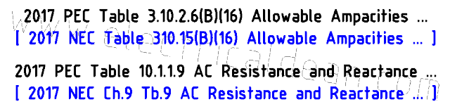
(2017 PEC Table 3.10.2.6(B)(16) [ or 2017 NEC Table 310.15(B)(16) ] Allowable Ampacities...)
In 2017 PEC Example D12, a 14mm^2, 65A THW wire size is selected. However, it does not take into consideration the possibility of a 4-wire system (3-phase with neutral) inside raceways, and therefore does not match the specification of going above the minimum requirements. It shall be deferred and the higher rating shall be chosen.
4.3.) The raceway shall match Specification 3.3.
a,wire = 30 mm^2 THW
a,insu ~= 86.6 mm^2
(2017 PEC Table 10.1.1.5 [ or 86.00 mm^2 in 2017 NEC Ch.9 Tb.5 ] Dimensions of Insulated...)
a,rcwy >= (5 * 86.6) / 0.4
a,rcwy >= 1,082.5 mm^2 [100% Area]
d,rcwy >= 37.1252 mm (~ 1.4616 in)
d,rcwy ~= 40 mm dia. (~ 1.5 in.) Trade Size, PVC Schedule 80
(2017 PEC Table 10.1.1.4 [ or 2017 NEC Ch.9 Tb.4 ] Dimensions and Percent Area...)
CONCLUSION
The 3-phase circuit breaker shall have a trip rating of 70 Amperes. The wires shall be 30 mm^2, 100A, Copper, 75degC THW. The raceway shall be 40 mm diameter (~ 1.5 inches) Trade Size rigid PVC Schedule 80 conduit.
==========
REFERENCES
1.) Philippine Electrical Code (SI Modernized Metric System)
1.1.) 2017 PEC 2.15.1.2(A)(1)(a) Feeders Not More Than 600 Volts.
1.2.) 2017 PEC 2.15.1.3 Feeders, Overcurrent Protection.
1.3.) 2017 PEC Table 2.40.1.6(A) Standard Ampere Ratings for Fuses and Inverse Time Circuit Breakers.
1.4.) 2017 PEC Table 3.10.2.6(B)(3)(a) Adjustment Factors for More Than Three Current-Carrying Conductors.
1.5.) 2017 PEC Table 3.10.2.6(B)(16) Allowable Ampacities of Insulated Conductors Rated Up to and Including 2000 Volts, 60degC Through 90degC, Not More Than Three Current-Carrying Conductors in Raceway, Cable, or Earth (Directly Buried), Based on Ambient Temperature of 30degC.
1.6.) 2017 PEC Table 10.1.1.1 Percent of Cross Section of Conduit and Tubing for Conductors.
1.7.) 2017 PEC Table 10.1.1.4 Dimensions and Percent Area of Conduit and Tubing (Areas of Conduit or Tubing for the Combinations of Wires Permitted in Table 10.1.1.1).
1.8.) 2017 PEC Table 10.1.1.5 Dimensions of Insulated Conductors and Fixture Wires.
1.9.) 2017 PEC Appendix D Example D11 Voltage Regulators, Three-Phase, 60 Hz, 350-530 Volts Input, 230 Volts Output VR.
2.) National Electrical Code (US Inch-Pound System)
2.1.) 2017 NEC 215.2(A)(1)(a) Feeders Not More Than 600 Volts.
2.2.) 2017 NEC 215.3 Feeders, Overcurrent Protection.
2.3.) 2017 NEC Table 240.6(A) Standard Ampere Ratings for Fuses and Inverse Time Circuit Breakers.
2.4.) 2017 NEC Table 310.15(B)(3)(a) Adjustment Factors for More Than Three Current-Carrying Conductors.
2.5.) 2017 NEC Table 310.15(B)(16) Allowable Ampacities of Insulated Conductors Rated Up to and Including 2000 Volts, 60degC Through 90degC (140degF Through 194degF), Not More Than Three Current-Carrying Conductors in Raceway, Cable, or Earth (Directly Buried), Based on Ambient Temperature of 30degC (86degF).
2.6.) 2017 NEC Chapter 9 Table 1 Percent of Cross Section of Conduit and Tubing for Conductors.
2.7.) 2017 NEC Chapter 9 Table 4 Dimensions and Percent Area of Conduit and Tubing (Areas of Conduit or Tubing for the Combinations of Wires Permitted in Table 1, Chapter 9).
2.8.) 2017 NEC Chapter 9 Table 5 Dimensions of Insulated Conductors and Fixture Wires.
2.9.) [Not found in 2017 NEC Annex D] (Voltage Regulators, Three-Phase, 60 Hz, 350-530 Volts Input, 230 Volts Output VR).

Comments
Post a Comment