Faults - Scenario 8
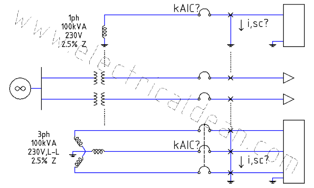
This post is a single-phase version of the three-phase example in the previous scenario without any motors present in the adjacent circuits. The goal here is to examine what magnitudes are to be expected in single-phase circuits compared to three-phase circuits, and how these magnitudes factor into the selection of protective device ratings.
SITUATION
An industrial complex receives 230 V, 60 Hz from a single-phase distribution transformer rated 300 kVA and an impedance of 5%. The transformer taps into a single-phase 34.5 kV supply with a 1,000 MVA short-circuit capacity.
Using the per-unit method, what maximum symmetrical fault currents may occur in each of the fault points "a", "b", and "c"? From these fault currents, what are the minimum symmetrical kiloAmpere Interrupting Capacity (kAIC) ratings needed for each molded case circuit breaker (MCCB) A, B, and C?

ANALYSIS
1.) ESTABLISH COMMON BASE VALUES.
New base power, 1ph: S,base,new = 300 kVA
No need to establish a common base voltage. By retaining the existing base voltages, the per-unit supply voltage for each sub-circuit is pegged at 1 pu.
2.) CONVERT PER-UNIT VALUES FROM THE GIVEN BASE VALUE TO THE COMMON BASE VALUE.
2.1.) SOURCE SUB-CIRCUIT
Actual power, 1ph: S,src,1ph = 1,000 MVA
Actual voltage, 1ph: V,src,1ph = 34.5 kV
Actual impedance, 1ph: Z,src,1ph = (V,src,1ph)^2 / S,src,1ph
For the source sub-circuit, the actual values can be used as given base values.
Base power, 1ph: S,base = S,src,1ph
Base voltage, 1ph: V,base = V,src,1ph
Base impedance, 1ph: Z,base = (V,base)^2 / S,base
2.1.1.) Source impedance, given, per-unit:
Z,src,pu = Z,src,1ph / Z,base
Z,src,pu = [ (V,src,1ph)^2 / S,src,1ph ] / [ (V,base)^2 / S,base ]
Z,src,pu = [ (V,src,1ph)^2 / S,src,1ph ] / [ (V,src,1ph)^2 / S,src,1ph ]
Z,src,pu = 1 pu
2.1.2.) Source impedance, new, per-unit:
Z,src,new,pu = Z,src,1ph / Z,base,new
Z,src,new,pu = Z,src,pu * Z,base / Z,base,new
Z,src,new,pu = Z,src,pu * (V,base^2 / S,base) / (V,base^2 / S,base,new)
Z,src,new,pu = Z,src,pu * V,base^2 * S,base,new / (V,base^2 * S,base)
Z,src,new,pu = Z,src,pu * S,base,new / S,src,1ph
Z,src,new,pu = 1 * 300 kVA / 1,000 MVA
Z,src,new,pu = 0.0003 pu
2.2.) TRANSFORMER LOAD-SIDE SUB-CIRCUIT
Base power, 1ph: S,base = 300 kVA
Base voltage, 1ph: V,base = 230 V
Base impedance, 1ph: Z,base = (V,base)^2 / S,base
2.2.1.) Transformer impedance, given, per-unit: Z,xmr,pu = 5% = 0.05 pu
2.2.2.) Transformer impedance, new, per-unit:
Z,xmr,new,pu = Z,xmr,1ph / Z,base,new
Z,xmr,new,pu = Z,xmr,pu * Z,base / Z,base,new
Z,xmr,new,pu = Z,xmr,pu * (V,base^2 / S,base) / (V,base^2 / S,base,new)
Z,xmr,new,pu = Z,xmr,pu * V,base^2 * S,base,new / (V,base^2 * S,base)
Z,xmr,new,pu = Z,xmr,pu * S,base,new / S,base
Z,xmr,new,pu = 0.05 pu * 300 kVA / 300 kVA
Z,xmr,new,pu = 0.05 pu
2.2.3.) Conductor impedance, 1L:
For the cable conductors in the load-side circuit, their specifications are 250 mm^2 THW in steel conduit at 100 ft long (30.4878 m).
According to 2017 PEC Table 10.1.1.9 [ or 2017 NEC Chapter 9 Table 9 ] AC Resistance and Reactance for 600 V Cables, the resistance and reactance for such specification are 0.029 ohms per 305 meters and 0.048 ohms per 305 meters, respectively. [ 305 meters ~= 1,000 feet ]
Z,wire,1L = [ (0.029 + j0.048) ohms / 305 m ] * 30.5 m
Z,wire,1L = (0.0029 + j0.0048) ohms
Z,wire,1L = 0.005608 ohms < 58.86 deg
2.2.4.) Conductor impedance, per-unit:
Z,wire,pu = Z,wire,1L / Z,base,new
Z,wire,pu = Z,wire,1L / (V,base^2 / S,base,new)
Z,wire,pu = 0.005608 ohms / (230V^2 / 300 kVA)
Z,wire,pu = 0.0318 pu
3.) FAULT CALCULATIONS
3.1.) AT FAULT POINT "a"
3.1.1.) One-line diagram for circuit at fault point "a":
o|---V,pu---Z,a,pu---"a"---|>

o|---V,pu---Z,src,new,pu---Z,xmr,new,pu---"a"---|>
3.1.2.) Short-circuit current at fault point "a", per-unit:
i,a,pu = V,pu / Z,a,pu
i,a,pu = V,pu / (Z,src,new,pu + Z,xmr,new,pu)
i,a,pu = 1 / (0.0003 + 0.05)
i,a,pu = 19.8807 pu
3.1.3.) Short-circuit current at fault point "a", 1ph:
i,a,sc = i,a,pu * i,base,new
i,a,sc = i,a,pu * S,base,new / V,base
i,a,sc = 19.8807pu * 300kVA / 230V
i,a,sc = 25,931.3478 Amps
i,a,sc = 25.931 kiloAmps
3.1.4.) Minimum interrupting capacity of MCCB A:
1-phase molded case circuit breaker A >= 26 kAIC symmetrical
3.2.) AT FAULT POINT "b"
3.2.1.) One-line diagram for circuit at fault point "b":
o|---V,pu---Z,b,pu---"b"---|>

o|---V,pu---|---Z,src,new,pu---Z,xmr,new,pu---|---"b"---|>
3.2.2.) Short-circuit current at fault point "b", per-unit:
i,b,pu = V,pu / Z,b,pu
Z,b,pu = (Z,src,new,pu + Z,xmr,new,pu)
Z,b,pu = 0.0003 + 0.05
Z,b,pu = 0.0503 pu
i,b,pu = 1 / 0.0503
i,b,pu = 19.8807 pu
3.2.3.) Short-circuit current at fault point "b", 1ph:
i,b,sc = i,b,pu * i,base,new
i,b,sc = i,b,pu * S,base,new / V,base
i,b,sc = 19.8807pu * 300kVA / 230V
i,b,sc = 25,931.3478 Amps
i,b,sc = 25.931 kiloAmps
3.2.4.) Minimum interrupting capacity of MCCB B:
1-phase molded case circuit breaker B >= 26 kAIC symmetrical
3.3.) AT FAULT POINT "c"
3.3.1.) One-line diagram for circuit at fault point "c":
o|---V,pu---Z,c,pu---"c"---|>

o|---V,pu---|---Z,src,new,pu---Z,xmr,new,pu---|---Z,wire,pu---"c"---|>
3.3.2.) Short-circuit current at fault point "c", per-unit:
i,c,pu = V,pu / Z,c,pu
Z,c,pu = (Z,src,new,pu + Z,xmr,new,pu) + Z,wire,pu
Z,c,pu = (0.0003 + 0.05) + 0.0318
Z,c,pu = 0.0503 + 0.0318
Z,c,pu = 0.0821 pu
i,c,pu = 1 / 0.0821
i,c,pu = 12.1803 pu
3.3.3.) Short-circuit current at fault point "c", 1L:
i,c,sc = i,c,pu * i,base,new
i,c,sc = i,c,pu * S,base,new / V,base
i,c,sc = 12.1803pu * 300kVA / 230V
i,c,sc = 15,887.3478 Amps
i,c,sc = 15.887 kiloAmps
3.3.4.) Minimum interrupting capacity of MCCB C:
1-phase molded case circuit breaker C >= 16 kAIC symmetrical
CONCLUSION
All fault points in this single-phase system experience significantly larger fault currents compared to the previous three-phase scenario. Although the per-unit currents are the same, the actual currents in the single-phase system are concentrated on one circuit instead of being distributed over three circuits "firing" their sine waves in succession "120 degrees" apart in the time domain [ | tan (120 deg) | = square root of 3 ].
The maximum symmetrical fault currents are 25.931 kiloAmperes at point "a", 25.931 kiloAmperes at point "b", and 15.887 kiloAmperes at point "c".
The minimum symmetrical kiloAmpere Interrupting Capacity ratings needed then is 26 kAIC for 1ph MCCB A, 26 kAIC for 1ph MCCB B, and 16 kAIC for 1ph MCCB C.
==========
REFERENCES
1.) Philippine Electrical Code (SI Modernized Metric System)
1.1.) 2017 PEC Table 10.1.1.9 Alternating-Current Resistance and Reactance for 600-Volt Cables, 3-Phase, 60Hz, 75degC - Three Single Conductors in Conduit.
1.2.) 2017 PEC Appendix D Example D14 Simplified Fault Current Calculation.
2.) National Electrical Code (US Inch-Pound System)
2.1.) 2017 NEC Chapter 9 Table 9 Alternating-Current Resistance and Reactance for 600-Volt Cables, 3-Phase, 60Hz, 75degC (167degF) - Three Single Conductors in Conduit.
2.2.) [Not found in 2017 NEC Annex D] (Simplified Fault Current Calculation).

Comments
Post a Comment