Posts

Showing posts from July, 2018

https://www.vultr.com

The Everywhere Cloud

Deploy an instance.
Accelerate your application.


Circuits - Scenario 3

Image
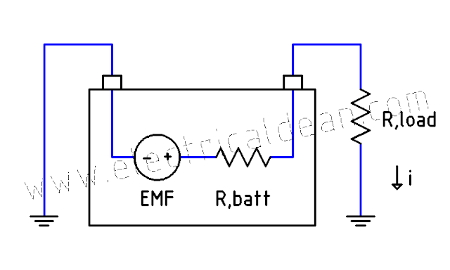
SITUATION A defective battery is found to have excessive heat losses during quality control tests. How its internal resistance determined to verify if it matches with its original design specification? ANALYSIS 1.) One-line diagram: o|---EMF,batt---R,batt---R,load---|> EMF,batt = battery internal electromotive force R,batt = battery internal resistance R,load = dummy load resistance 2.) Ohm's Law: V,load = i * R,load i = V,load / R,load 3.) KVL: (-EMF,batt) + i * (R,batt + R,load) = 0 (-EMF,batt) + (V,load / R,load) * (R,batt + R,load) = 0 (-EMF,batt) + (V,load / R,load) * R,batt + V,load = 0 V,load (R,batt / R,load) = EMF,batt - V,load R,batt / R,load = (EMF,batt / V,load) - 1 R,batt = [ (EMF,batt / V,load) - 1 ] * R,load At no load: V,NL = EMF,batt At full load: V,FL = V,load R,batt = [ (V,NL / V,FL) - 1 ] * R,load CONCLUSION The internal resistance of a battery can be determined by measuring its no-load voltage, then placing a known resi

Trivia - Electric Mnemonic 2

Image
This post presents an alternative way of memorizing the color code of resistors. 1.) Resistor colors are arranged as follows: Black (0), Brown (1), Red (2), Orange (3), Yellow (4), Green (5), Blue (6), Violet (7), Gray (8), White (9) 2.) At first glance, they may seem hard to remember even though there are only ten of them. But upon closer inspection, the colors are logically arranged from "darkest" to "lightest". BB, ROYGBV, GW Therefore, they can be categorized to shorten memorization, with only a few colors per category. "2 Dark, 6 Rainbow, 2 Light" or simply, "Dark Rainbow Light" 3.) For those who like to memorize on per-letter basis, they can also be expanded into "sentence" form. BB ROYGBV GW "Bell Boy ROY G. BiV Gets Water" "Boss Baby ROY G. BiV Got Wet" "Bad Boy ROY G. BiV Gave Weapons" "Big Bad ROY G. BiV Goes Wild" ... and so on. 4.) As for resistor tole

Loads - Scenario 3

Image
SITUATION Lamp 1 and Lamp 2, operating in parallel across 230 Volts, dissipate rated power at 100 Watts and 60 Watts respectively. How much power will each lamp dissipate if they are connected in series? ANALYSIS 1.) Parallel operation 1.1.) Power: P,1 = 100W P,2 = 60W 1.2.) Resistance: R,1 = (V)^2 / P,1 R,1 = (230V)^2 / 100W = 529 ohms R,2 = (V)^2 / P,2 R,2 = (230V)^2 / 60W = 881.67 ohms 2.) Series operation 2.1.) Current: V = i * (R,1 + R,2) i = V / (R,1 + R,2) i = 230V / [(529 + 881.67) ohms] i = 0.16A 2.2.) Power: P,1 = i^2 * R,1 P,1 = (0.16A)^2 * 529 ohms = 13.54W P,2 = i^2 * R,2 P,2 = (0.16A)^2 * 881.67 ohms = 22.57W CONCLUSION When connected in series, Lamp 1 dissipates around 13.5 Watts while Lamp 2 dissipates around 22.6 Watts. Both outputs decrease significantly, but Lamp 2 now has a higher power output than Lamp 1.

Circuits - Scenario 2

Image
This post presents a simple circuit that can be thought of as a basic model for wire insulation. When insulators weaken, high voltages can push stray currents out, hence the need for insulation resistance tests. SITUATION A 40-picoFarad capacitor is connected in series with 40-ohm resistor. If the supply is 220 Volts at 60 Hertz, what is the current flowing through the circuit? ANALYSIS 1.) Capacitive reactance, vector: X-> = 1 / (jwC) = -j / (2 pi f C) 2.) Impedance, vector: Z-> = R-> + X-> Z-> = 40 + [ -j / (2 pi 60 * 40p) ] Z-> = (40 - j 66.315M) ohms Z-> = 66.315M ohms < (-89.999965) 3.) Current, vector: i-> = V-> / Z-> i-> = 220V<0 / [ 66.315M ohms < (-89.999965) ] i-> = 3.3175uA < 89.999965 CONCLUSION The current is 3.3176 microAmperes, leading.

Circuits - Scenario 1

Image
This post presents a simple circuit that can be thought of as a basic model for conductor cables in large wiring installations, such as in big residential apartments, tall commercial buildings, or wide industrial complexes, where short-circuit or ground fault currents may not be enough to kick a circuit breaker open. In such cases, the fault condition will simply become what is known as a "phantom load". It unnecessarily heats up the cable and contributes to the energy consumption even when electrical appliances are unplugged. As cable length increases, conductor resistance and reactance become more evident, hence the need to consider them carefully in wiring design calculations. SITUATION A 0.0001-henry inductor is connected in series with 40-ohm resistor. If the supply is 220 Volts at 60 Hertz, what is the current flowing through the circuit? ANALYSIS 1.) Inductive reactance, vector: X-> = jwL = j 2 pi f L 2.) Impedance, vector: Z-> = R-> + X-&

Faults - Scenario 4

Image
This post demonstrates how to estimate the kiloAmpere Interrupting Capacity (kAIC) rating of the first circuit breaker at the secondary side of a transformer using the Infinite Bus Method. The method assumes infinite supply from the primary side with negligible line impedances. Below is a modified version of Example D13 (Available Short Circuit Current)  in Appendix D of the 2017 Philippine Electrical Code (PEC). SITUATION Two adjacent buildings are supplied by two different distribution transformers. One transformer is single-phase rated 100kVA, 230V with 2.5% impedance. The other is three-phase rated 100kVA, 230V line-to-line and also has 2.5% impedance. What minimum kAIC ratings are needed for the first circuit breakers down the line of each transformer to safely interrupt the maximum symmetrical fault currents? ANALYSIS 1.) SINGLE-PHASE TRANSFORMER LOAD-SIDE SUB-CIRCUIT Base Power, 1ph: S,base = 100kVA Base Voltage, 1ph: V,base = 230V Impedance, given: Z

Faults - Scenario 3

Image
This post demonstrates how the Infinite Bus Method, shown in Appendix D Example D13 (Available Short Circuit Current) of the 2017 Philippine Electrical Code (PEC), can also be used to estimate fault currents for three-phase circuits. SITUATION A three-phase fault occurs down the line of a three-phase transformer rated 10MVA, 4.16 kiloVolts, and 5.5% impedance. What is the maximum symmetrical fault current produced? ANALYSIS 1.) TRANSFORMER LOAD-SIDE SUB-CIRCUIT Base power, 3ph: S,base = 10MVA Base voltage, LL: V,base = 4.16kV Impedance, given: Z = 5.5% 1.1.) Establishing mathematical relationships to avoid confusion: S,base = S,3ph V,base = V,LL V,LN = V,LL / sqrt(3) i,1ph = i,1L (assuming Y-config) i,base = i,1L S,3ph = 3 * V,LN * i,1ph S,3ph = 3 * ( V,LL/sqrt(3) ) * i,1L S,3ph = 3/sqrt(3) * V,LL * i,1L S,3ph = [ 3/sqrt(3) * ( sqrt(3) / sqrt(3) ) ] * V,LL * i,1L S,3ph = [ 3 * sqrt(3) / sqrt(3)^2 ] * V,LL * i,1L S,3ph = [ 3 * sqrt(3) / 3 ] * V,LL * i,